
In this blog post, I will share on the configuration of TP-Link SG108E switch. Before we start, the important terminology you need to know for now is Trunk port means “tagged” and Access ports are “untagged”.
The default configuration of the switch are as follows:
- IP: 192.168.0.1/24
- Username: admin
- Password: admin
The configurations that we will be doing are as follows
- Changing of Default Switch IP from 192.168.0.1 to 192.168.9.10
- VLAN 10 (Management) —> Port 1 to Port 3 Access / Native, Port 8 Trunk
- VLAN 11 (Prod1) —> Port 1 to Port 3 Trunk, Port 8 Trunk
- VLAN 12 (Prod2) —> Port 1 to Port 3 Trunk, Port 8 Trunk
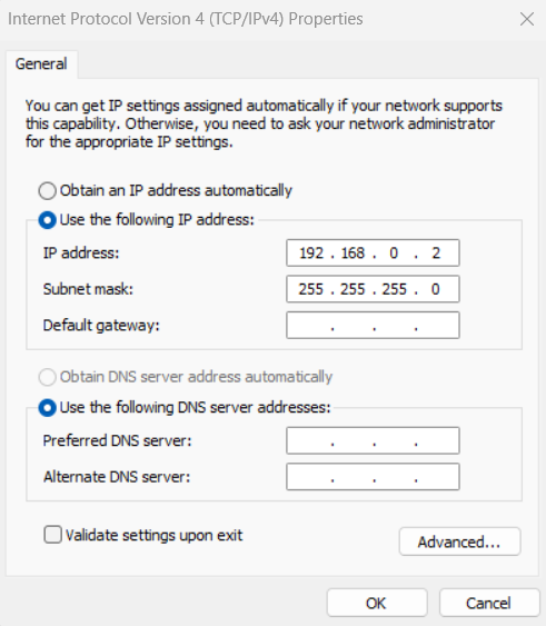
Step 1: Let’s connect to the switch’s default IP. In order to do this, we will have to change our management laptop IP to be in that switch default IP range, e.g. 192.168.0.2/24
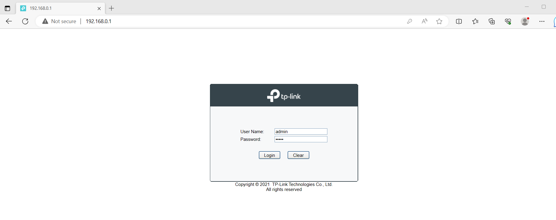
Step 2: Login with the default username and password
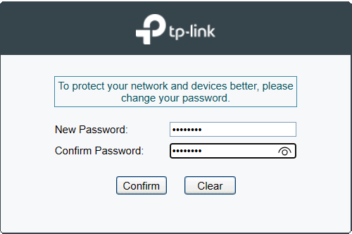
Step 3: You will be prompted to change password
Step 4: Change the default switch IP to 192.168.9.10. You can do so by clicking on “System” -> “IP Setting” -> Choose DHCP Setting as “Disabled” and enter the following values and click “Apply”.
- IP Address: 192.168.9.10
- Subnet Mask: 255.255.255.0
- Default Gateway: 192.168.9.254

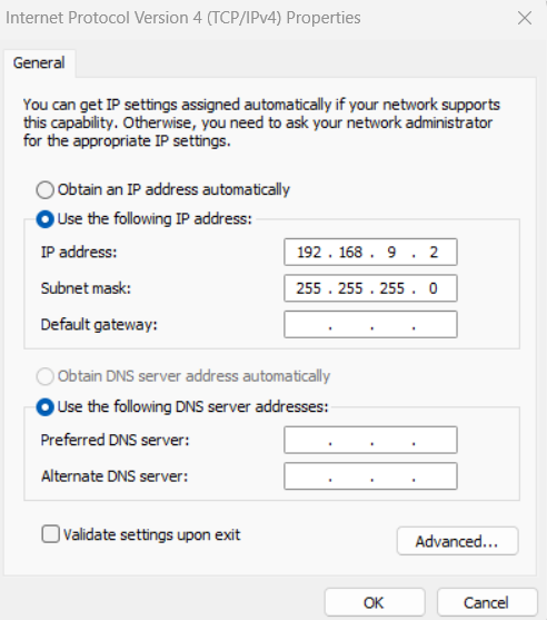
Step 5: Change your management laptop IP to be in 192.168.9.0/24 range, e.g. 192.168.9.2/24
Step 6: Enter 192.168.9.10 into your web browser and login to the switch management console again using “admin” as the username and password as the password you entered in Step 3.

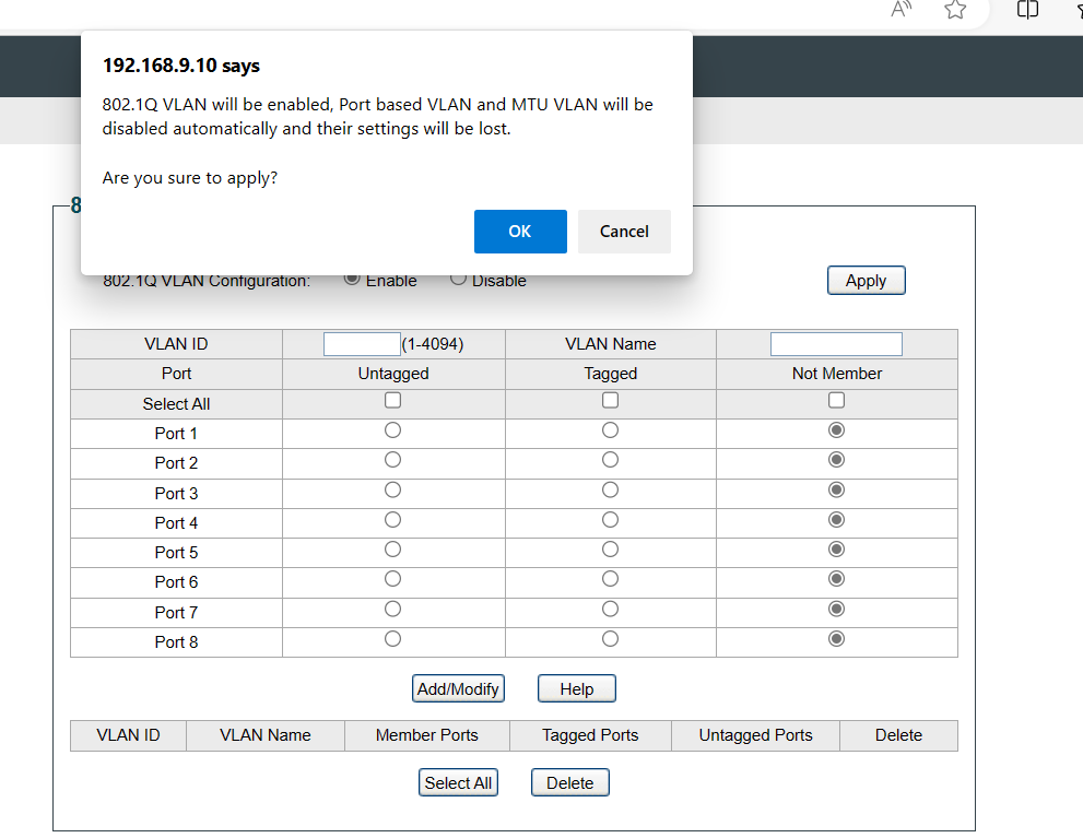
Step 7: Click the “VLAN” menu and choose “802.1Q VLAN” option. Select “Enable”, click “Apply” and click “Ok”
Step 8: Let’s create VLAN 10 with its desired configuration. Let’s enter the configuration as follows
- VLAN ID = 10
- VLAN Name = Management
- Select Port 1 to Port 3 as untagged
- Select Port 8 as tagged
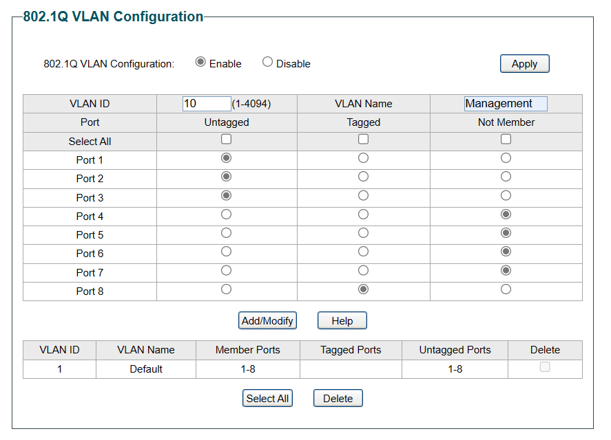
Step 9: Click “Add/Modify” and you should see the output as below
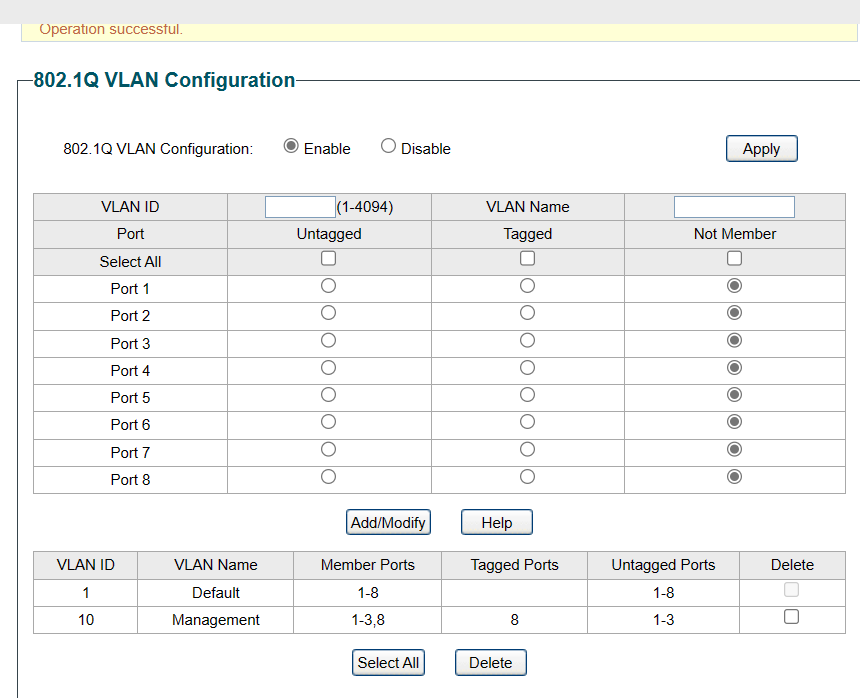
Step 10: Repeat Step 8 and Step 9 and you should see the output as below
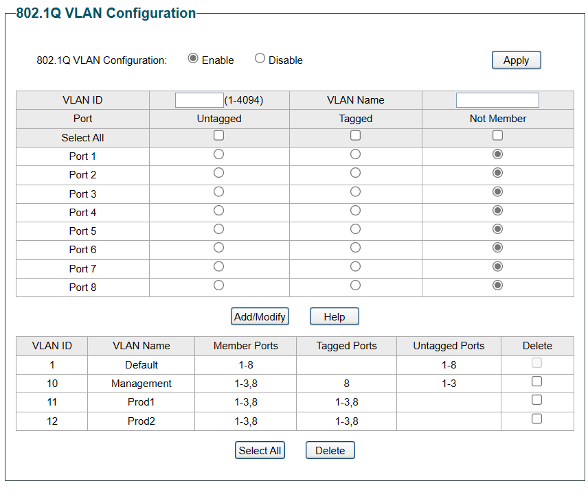
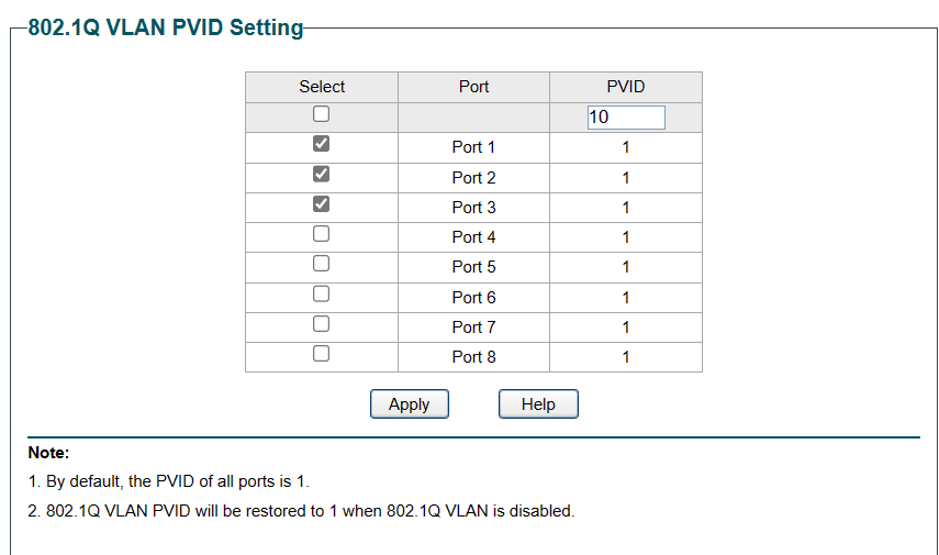
Step 11: Let’s configure native VLAN 10 for Port 1 to Port 3. Still on the VLAN menu, choose “802.1Q PVID Setting”. Select Port 1 to Port 3 and enter “10” in the PVID box.
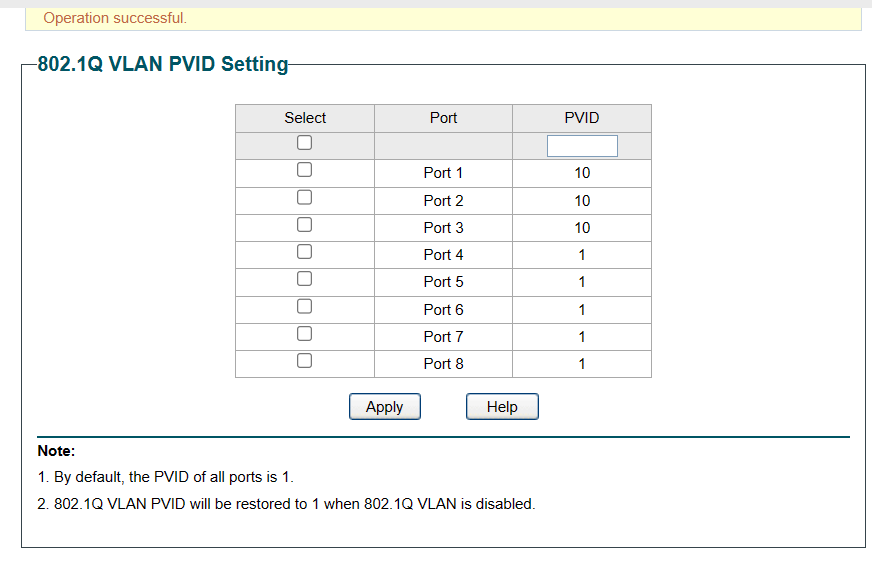
Step 12: Click “Apply” and you should have the output below
Step 13: Connect the switch’s Port 8 to ER-X’s Port 2
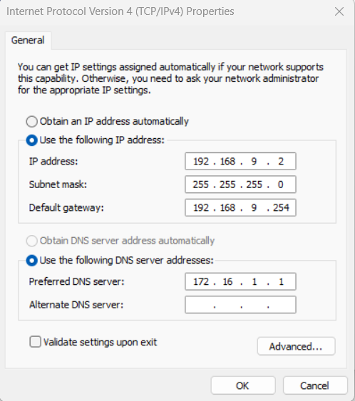
Step 14: Connect your management laptop to Port 4 and configure IP setting as the following.
- IP Address: 192.168.9.2
- Subnet Mask: 255.255.255.0
- Default Gateway: 192.168.9.254
- DNS: 172.16.1.1
Step 15: Perform a ping to http://www.google.com and you should have a response

In the next blog post, I will share on the installation of Nutanix nodes.

You must be logged in to post a comment.